Basic Configuration Commands | |
Command | Purpose |
| enable | Logs you into enable mode, which is also known as user exec mode or privileged mode |
| configure terminal | Logs you into configuration mode |
| interface fastethernet/number | Enters interface configuration mode for the specified fast ethernet interface |
| reload | An exec mode command that reboots a Cisco switch or router |
| hostname name | Sets a host name to the current Cisco network device |
| copy from-location to-location | An enable mode command that copies files from one file location to another |
| copy running-config startup-config | An enable mode command that saves the active config, replacing the startup config when a Cisco network device initializes |
| copy startup-config running-config | An enable mode command that merges the startup config with the currently active config in RAM |
write erase
erase startup-config
| An enable mode command that deletes the startup config |
| ip address ip-address mask | Assigns an IP address and a subnet mask |
shutdown
no shutdown
| Used in interface configuration mode. “Shutdown” shuts down the interface, while “no shutdown” brings up the interface. |
| ip default-gateway ip_address | Sets the default gateway on a Cisco device |
| show running-config | An enable mode command that displays the current configuration |
| description name-string | A config interface command to describe or name an interface |
| show running-config interface interface slot/number | An enable mode command to display the running configuration for a specific interface |
| show ip interface [type number] | Displays the usability status of interfaces that are configured for IP |
| ip name-server serverip-1 serverip-2 | A configure mode command that sets the IP addresses of DNS servers |
Troubleshooting Commands | |
| ping {hostname | system-address} [source source-address] | Used in enable mode to diagnose basic network connectivity |
| speed {10 | 100 | 1000 | auto} | An interface mode command that manually sets the speed to the specified value or negotiates it automatically |
| duplex {auto | full | half} | An interface mode command that manually sets duplex to half, full or auto |
cdp run
no cdp run
| A configuration mode command that enables or disables Cisco Discovery Protocol (CDP) for the device |
| show mac address-table | Displays the MAC address table |
| show cdp | Shows whether CDP is enabled globally |
| show cdp neighbors[detail] | Lists summary information about each neighbor connected to this device; the “detail” option lists detailed information about each neighbor |
| show interfaces | Displays detailed information about interface status, settings and counters |
| show interface status | Displays the interface line status |
| show interfaces switchport | Displays a large variety of configuration settings and current operational status, including VLAN trunking details. |
| show interfaces trunk | Lists information about the currently operational trunks and the VLANs supported by those trunks |
show vlan
show vlan brief
| Lists each VLAN and all interfaces assigned to that VLAN but does not include trunks |
| show vtp status | Lists the current VTP status, including the current mode |
Routing and VLAN Commands | |
| ip routenetwork-number network-mask {ip-address | interface} | Sets a static route in the IP routing table |
| router rip | Enables a Routing Information Protocol (RIP) routing process, which places you in router configuration mode |
| network ip-address | In router configuration mode, associates a network with a RIP routing process |
| version 2 | In router configuration mode, configures the software to receive and send only RIP version 2 packets |
| no auto-summary | In router configuration mode, disables automatic summarization |
| default-information originate | In router configuration mode, generates a default route into RIP |
| passive-interface interface | In router configuration mode, sets only that interface to passive RIP mode. In passive RIP mode, RIP routing updates are accepted by, but not sent out of, the specified interface. |
| show ip rip database | Displays the contents of the RIP routing database |
| ip nat [inside | outside] | An interface configuration mode command to designate that traffic originating from or destined for the interface is subject to NAT |
| ip nat inside source {list{access-list-number | access-list-name}} interface type number[overload] | A configuration mode command to establish dynamic source translation. Use of the “list” keyword enables you to use an ACL to identify the traffic that will be subject to NAT. The “overload” option enables the router to use one global address for many local addresses. |
| ip nat inside source static local-ip global-ip | A configuration mode command to establish a static translation between an inside local address and an inside global address |
| vlan | Creates a VLAN and enters VLAN configuration mode for further definitions |
| switchport access vlan | Sets the VLAN that the interface belongs to. |
| switchport trunk encapsulation dot1q | Specifies 802.1Q encapsulation on the trunk link. |
| switchport access | Assigns this port to a VLAN |
| vlan vlan-id [name vlan-name] | Configures a specific VLAN name (1 to 32 characters) |
| switchport mode { access | trunk } | Configures the VLAN membership mode of a port. The access port is set to access unconditionally and operates as a non-trunking, single VLAN interface that sends and receives non-encapsulated (non-tagged) frames. An access port can be assigned to only one VLAN. The trunk port sends and receives encapsulated (tagged) frames that identify the VLAN of origination. A trunk is a point-to-point link between two switches or between a switch and a router. |
| switchport trunk {encapsulation { dot1q } | Sets the trunk characteristics when the interface is in trunking mode. In this mode, the switch supports simultaneous tagged and untagged traffic on a port. |
| encapsulation dot1q vlan-id | A configuration mode command that defines the matching criteria to map 802.1Q frames ingress on an interface to the appropriate service instance |
DHCP Commands | |
| ip address dhcp | A configuration mode command to acquire an IP address on an interface via DHCP |
| ip dhcp pool name | A configuration mode command to configure a DHCP address pool on a DHCP server and enter DHCP pool configuration mode |
| domain-name domain | Used in DHCP pool configuration mode to specify the domain name for a DHCP client |
| network network-number [mask] | Used in DHCP pool configuration mode to configure the network number and mask for a DHCP address pool primary or secondary subnet on a Cisco IOS DHCP server |
| ip dhcp excluded-address ip-address [last-ip-address] | A configuration mode command to specify IP addresses that a DHCP server should not assign to DHCP clients |
| ip helper-address address | An interface configuration mode command to enable forwarding of UDP broadcasts, including BOOTP, received on an interface |
| default-router address[address2 ... address8] | Used in DHCP pool configuration mode to specify the default router list for a DHCP client |
Security Commands | |
| passwordpass-value | Lists the password that is required if the login command (with no other parameters) is configured |
| username name password pass-value | A global command that defines one of possibly multiple user names and associated passwords used for user authentication. It is used when the login local line configuration command has been used. |
| enable password pass-value | A configuration mode command that defines the password required when using the enable command |
| enable secretpass-value | A configuration mode command that sets this Cisco device password that is required for any user to enter enable mode |
| service password-encryption | A configuration mode command that directs the Cisco IOS software to encrypt the passwords, CHAP secrets, and similar data saved in its configuration file |
| ip domain-name name | Configures a DNS domain name |
| crypto key generate rsa | A configuration mode command that creates and stores (in a hidden location in flash memory) the keys that are required by SSH |
| transport input {telnet | ssh} | Used in vty line configuration mode, defines whether Telnet or SSH access is allowed into this switch. Both values can be specified in a single command to allow both Telnet and SSH access (default settings). |
| access-list access-list-number {deny | permit} source [source-wildcard] [log] | A configuration mode command that defines a standard IP access list |
| access-class | Restricts incoming and outgoing connections between a particular vty (into a basic Cisco device) and the addresses in an access list |
| ip access-list {standard | extended} {access-list-name | access-list-number} | A configuration mode command that defines an IP access list by name or number |
| permit source [source-wildcard] | Used in ACL configuration mode to set conditions to allow a packet to pass a named IP ACL. To remove a permit condition from an ACL, use the “no” form of this command. |
| deny source [source-wildcard] | Used in ACL configuration mode to set conditions in a named IP ACL that will deny packets. To remove a deny condition from an ACL, use the “no” form of this command. |
| ntp peer <ip-address> | Used in global configuration mode to configure the software clock to synchronize a peer or to be synchronized by a peer |
| switchport port-security | Used in interface configuration mode to enable port security on the interface |
| switchport port-security maximum maximum | Used in interface configuration mode to set the maximum number of secure MAC addresses on the port |
| switchport port-security mac-address {mac-addr | {sticky [mac-addr]}} | Used in interface configuration mode to add a MAC address to the list of secure MAC addresses. The “sticky” option configures the MAC addresses as sticky on the interface. |
| switchport port-security violation {shutdown | restrict | protect} | Used in interface configuration mode to set the action to be taken when a security violation is detected |
| show port security [interface interface-id] | Displays information about security options configured on the interface |
Monitoring and Logging Commands | |
| logging ip address | Configures the IP address of the host that will receive the system logging (syslog) messages |
| logging trap level | Used in configuration mode to limit messages that are logged to the syslog servers based on severity. Specify the number or name of the desired severity level at which messages should be logged. |
| show logging | Enable mode command that displays the state of system logging (syslog) and the contents of the standard system logging buffer. |
| terminal monitor | An enable mode command that tells Cisco IOS to send a copy of all syslog messages, including debug messages, to the Telnet or SSH user who issues this command |
Networking
Scripts and Configurations of network devices (Mikrotik, UBNT, Cisco, TP-Link)
Tuesday, 28 January 2020
Cisco Commands
NETWORKS FULL FORMS
TCP/IP – Transmission Control Protocol /
Internet Protocol
LAN – Local Area Network
MAN – Metropolitan Area Network
WAN – Wide Area Network
Modem – Modulation(tor)/Demodulation(tor)
URL – Uniform Resource Location
FTP – File Transfer Protocol
HTTP – Hyper Text Transfer Protocol
PPP – Point to Point Protocol
GSM – Global System for Mobile
CDMA – Code Division Multiple Access
WLL(WiLL)–Wireless in Local Loop
SMS – Short Message Service
WWW – World Wide Web
HTML – Hyper Text Markup Language
XML – eXtensible Markup Language
NFS – Network File System
ARPANET – Advanced Research
Projects Agency
NSFnet – National Science Foundation
NIU – Network Interface Unit
NIC - Network Interface Card
TAP – Terminal Access Point
(NIU = NIC = TAP)
VGM – Voice Grade Medium
DGM – Data Grade Medium
STP – Shielded Twisted Pair
UTP – Unshielded Twisted Pair
LED – Light Emitting Diode
LD – Laser Diode
Kbps – Kilo bits Per Second
KBps – Kilo Bytes Per Second
Mbps - Mega Bits Per Second
MBps – Mega Bytes Per Second
Gbps - Giga Bits Per Second
GBps – Giga Bytes Per Second
OFC – Optic Fiber Cable
Fiber Optic Cable
KHz – Kilo Hertz
MHz – Mega Hertz
GHz – Giga Hertz
THz – Tera Hertz
Bps – Bytes Per Second
bps - Bits Per Second
PDA – Personal Digital Assistants
P-P - Point to Point
AM – Amplitude Modulation
FM - Frequency Modulation
PM – Phase Modulation
A/F – Audio Frequency
(Txd – Transmit Rxd – Receive
RTS – Request to Send
CD – Carrier Detect
DSR – Data Set Ready
CTS – Clear to Send
DTR – Data Terminal Ready)
RJ45 – Registered Jack – 45
BNC – Bayone – Neill – Concelman
AUI – Attachment Unit Interface
SNA – Systems Network Architecture
VFIR – Very Fast Infrared
URI – Uniform Resource Identifier
URN – Uniform Resource Name
MIME – Mail and Multipurpose Internet
Mail Extensions
POP – Post Office Protocol
SMTP – Simple Mail Transfer Protocol
NNTP – Network News Transfer Protocol
HTTP – Hyper Text Transfer Protocol
NTP – Network Time Protocol
IMAP – Internet Mail Transfer Protocol
SLIP – Serial Line Internet Protocol
IPCP – IP Control Protocol
NCP – Network Control Protocol
LCP – Link Control Protocol
PC – Personal Computer
ISP – Internet Service Provider
SIM – Subscriber Identity Module
TDMA – Time Division Multiple Access
TDM – Time Division Multiplexing
IDEN – Integrated Digital Enhanced
Network
WCDMA –Wideband CDMA
PSTN – Public Switched Telephone
Network
3G – Third Generation
UMTS – Universal Mobile
Telecommunications System /
Universal Mobile Telephone
System
EDGE – Enhanced Data rates for Global Evolution
SMSC – Short Message Service Center
HLR – Home Location Register
Email – Electronic Mail
Fax – Fascimile
VSNL – Videsh Sanchar Nigam Limited
DNS – Domain Name Server
DHTML– Dynamic Hyper Text Markup Language
DECnet– Digital’s family of communication protocols
IE – Internet Explorer
Saturday, 17 March 2018
Mikrotik configuration for Point-to-Point devices
MikroTik configuration for point-to-point
MikroTik equipment configuration is made through the program called Winbox. You can download it via the link: http: //router_address/winbox/winbox.exe (where router_address is device address, respectively). Also you can go to the device through the web interface and download winbox through the link. The first thing we do - reset factory settings.
Reset Mikrotik to factory settings
1. If you are connected to the device for the first time, the corresponding window titled RouterOS Default Configuration will appear immediately and you need to reset the settings by clicking on Remove Configuration.
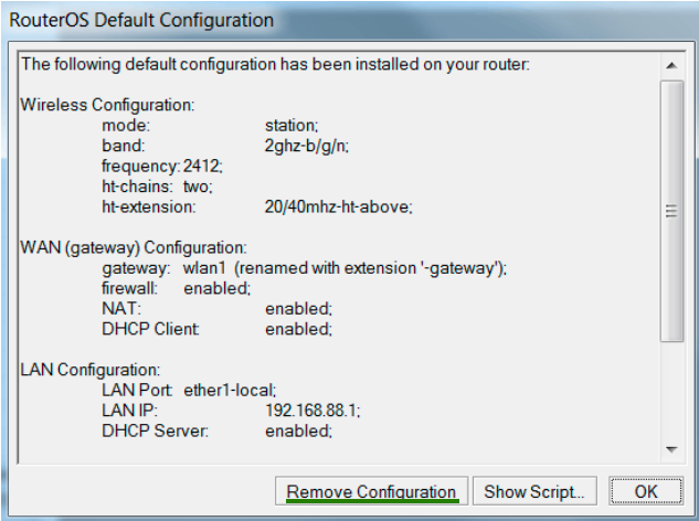
2. If you have already visited the device once, the default window won’t appear. Go to the New Terminal menu and with the system reset-configuration command restart the device (after reboot window with settings reset will appear).
Or go to the System menu, then - into Reset Configuration. Then tick No Default Configuration and click on Reset Configuration. Factory configuration had reset.
BRIDGE Settings
Adding ports so the traffic can be transmitted through MikroTik equipment on a wired and WiFi interface. Otherwise, our devices will only talk to each other. To do this, click + button in the Bridge menu (opens a window like in the image below), assign name for the bridge and click OK.
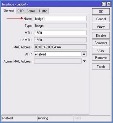
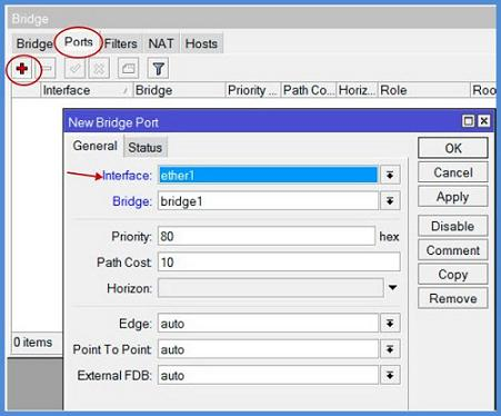
Go to the Ports tab, click on + and add the Wlan1 port on Interface line. On the Bridge line chose our previously createdbridge1. Hit OK. Click + again and create Ether1port:
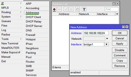
Assign IP-address for the bridge:
IPmenu => Adresses submenu => + button, enter bridge address and subnet mask. Filling lines after Network is optional.
Configuration in the Wireless menu
Select Wireless, then open Wlan1.
1. Wireless tab settings
Wireless interface parameters are set here:
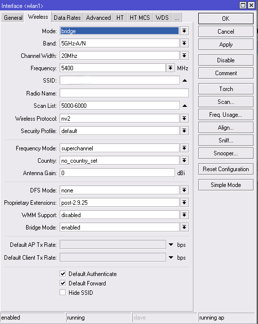
Mode - Now we are interested in:
- Bridge - BS mode for point-to-point
- AP Bridge - BS mode for point-to-multipoint.
There is also a mode for client workstations:
- Station - settings for a client device.
- Station WDS - settings for a client device with WDS support. (recommended to use on the client.)
Band - The first part of the value, up to a dash - is the frequency of operation, the second - supported standards. For the standards it is recommended to select only-N value, to raise the maximum speed.
On the client device, you can choose several options for standards, for example, expose 2GHz-B / G / N, then when you change settings on the BS customers you will reconnect automatically.
Channel Width - By default, put 20MHz. If you plan more than 100 Mbit / s and using Gigabit device - then you can use a 40MHz bandwidth.
Frequency - Select from the list or write manually.
SSID - The network name. It will be seen by the subscriber units.
Radio Name - The device name. For example, Vayudoot.
Scan List - Default, while using only the standard channels. You can specify a single frequency, multiple (separated by a comma), the range (with a dash), and can be combined. For example, a value of 2424, 2300-2500 will mean that the first device will start searching for the BS on the channel in 2424, in the absence of a response will go to the range 2300-2500, and will be looking there.
Wireless Protocol - equipment working protocols.
- 802.11 - normal protocol wi-fi, suitable for connection to a customers base station with laptops or USB adapters.
- Nstreme - the old polling protocol. If it is exposed in the settings, to the BS will connect only devices that support it.
- NV2 - the last polling protocol. We use it. Again, the connection will be available for devices that support this type of protocol. With laptop or USB adapter connection is impossible.
- Any - This mode is exhibiting for the subscribers. This enables connection to the BS at any exposed modes.
Security Profile - Normally - default.
Frequency Mode - Selection Mode for available frequencies and capacities
- Manual Txpower - This mode provides the ability to manually change the settings of the radio signal strength.
- Regulatory Domain - selection of operating mode with the parameters of power and frequency allowed for the particular country.
- Superchannel - In this mode, the power can be changed, as well as to use all available frequencies.
Country - Select a country to determine the list of frequencies that it is available.
Antenna Gain - Often not used, put 0 in field.
WMM Support< b> - Radio priorities.
Bridge Mode - Always - enabled.
Default Authenticate - When exposed tick – all devices can connect, tick removed - only those that are in the Allow list.
Default Forward - Exposed tick - restriction of data exchange between the connected client devices. This setting only works in 802.11 mode for laptops and devices without WDS support.
Hide SSID Exposed tick hides the name of the network (the network does not appear in the list if scanned). To connect, you must manually register the name of the client device.
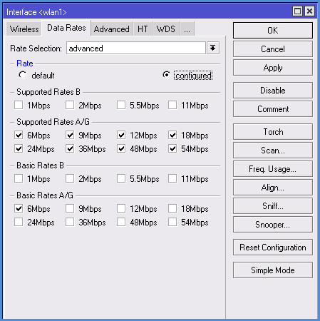
2. Settings on the Data Rates tab
If we choose N-only mode for our devices, all the checkboxes on this tab will be removed. Other - see settings below.
Rate Selection - Put the Advanced for our best configuration for devices.
Supported Rates - remove the ticks so devices will be using only a high-speed standard G and N.
Supported Rates A / G Expose all ticks.
Basic Rates B - remove all ticks.
Basic Rates A / G - Install only 6 M.
3. Settings in the Advanced tab
Max Station Count - The maximum number of client connections
Distance - The maximum distance to the subscriber stations
- Dynamic - the distance is determined automatically.
- Indoor - expose this value for data transfer indoors.
Noise Floor Threshold - The most common values are set ... -92 -107. You can also define it by yourself: to measure the noise level and reduce this figure by 5-10 units. For example: If the sound level -107, therefore, the value we put is -100.
Periodic Calibration - It is recommended to always include this option (enabled), so the device will automatically adjust to increase / decrease the noise level.
Calibration Interval - recommended to set for 10 seconds. Default is 1 minute.
Hw. Retries - The amount of data sent repeats unless the acknowledgment of receipt.
- Values between 1 and 5 - the speed of the connection is higher, but for users with poor signal connection stability gets worse (packet loss, frequent disconnections).
- Values between 5 and 10 - the golden middle.
- Values between 10 and 15 - the maximum guarantee delivery of data, but the problem network will slow down.
On this basis, for the base station preferably exhibit average values (5-7) and put the maximum channel-to-point - 15.
Hw. Protection Mode - Always put out RTS / CTS.
Adaptive Noise Immunity - It is recommended to activate the option AP and client mode for protection against interference when multiple base stations are close by.
Disconnect Timeout - The time period over which the client does not respond to the request, it will be disabled.
On Fail Retry Time - It is recommended to leave the 100 ms.
4. Settings in HT, HT MCS, WDS tabs
If our devices use MIMO (which is desirable since such equipment bandwidth is higher), then you need to pay attention to the appropriate setting antennas on the HTtab:
- HT Tx Chains - the receive channel, HT Rx Chains - the transmission channel. If you are using the MIMO, it is best to activate both antennas on reception and transmission (chain0, chain1). Of course, if there is only one antenna, then activate one channel.
- In the HT Guard Interval parameter ALWAYS put long, if you use the N standard for external links.
- HT Extension Channel - This parameter is used to add additional channels when using 40 MHz. Optimal values are established experimentally.
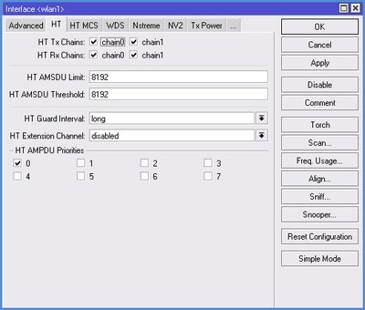
On the HT MCS tab it is recommended to leave the default values.
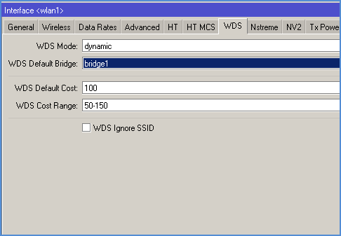
On the WDS tab we are interested in two parameters:
- WDS Mode - recommended to set mode Dynamic, while new customers bridge will be added automatically. In case of manually adding preferences, select Static.
- WDS Default Bridge - by default customers will be added to the specified field in the bridge. Therefore, we specify its name here: bridge1.
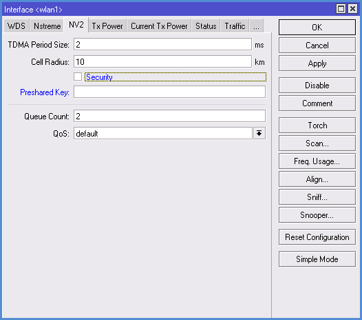
5. Settings in NV2 tab
Here we set the parameters of the MikroTik NV2 protocol (by the way, setting NSTREME Protocol and the relevant tab we do not consider because it is outdated and almost never used).
- TDMA Period Size - the time of transmission. For the base station 5-7 is recommended, for radio bridge - 1-2. Lower the value in this field, smaller the transmission delay is, but the rate decreases. And vice versa - increasing the value will mean more speed, but increased delay. The optimum value is selected by experimenting.
- Cell Radius - here we expose the distance to the remote client
- Security - enable / disable encryption protocol through NV2 protocol. This is a completely separate encryption mechanism unrelated to the fact that we will adjust the Security Profiles tab.
- Preshared Key - security key for connection to network, set same for all devices.
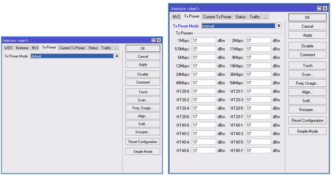
6. Settings for TX POWER tab
More often is set to Default. If you select Manual, the field with the settings will appear and you can manually adjust radio card power.
Encryption configuration
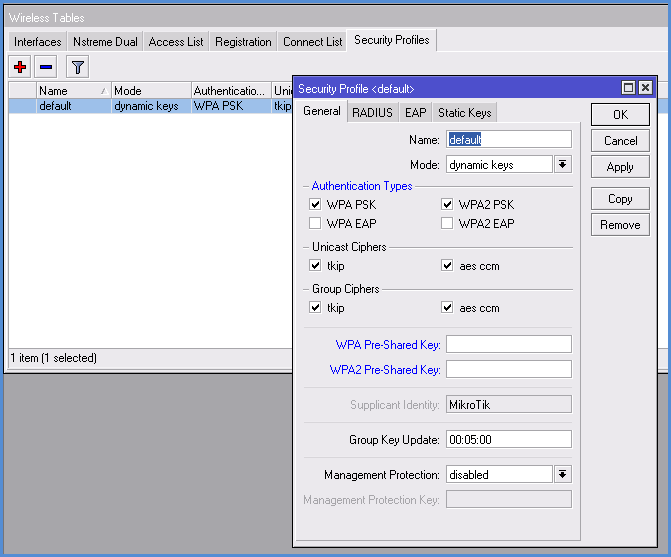
In the Wireless section, go to Security Profiles tab:
- Name - assign the encryption profile name.
- Mode - Select the encryption mode, often set Dynamic Keys.
- Authentication Types - put a tick on WPA PSK, WPA2 PSK or select both.
- Unicast Ciphers - Select the encryption algorithm. Recommended AES, because it supports radio card.
- Group Ciphers - the same settings as in the previous paragraph.
- WPA Pre-Shared Key - the code word for the WPA type of encryption. We put the same on all devices.
- WPA2 Pre-Shared Key - password for the WPA2 encryption type
Second device configuration
Most of the settings are identical, with the exception of:
- When you configure IP-addresses for the second point make it different from the first address.
- If you are configuring the wireless interface settings on the Wireless tab, specify: in the Mode - station wds, in the SSID - the name of the first point.
Views of connection compounds
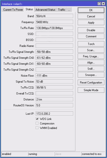
If we set up all correctly, you can see parameters in the Status tab:
Band - The frequency and standard of work points (Mode)
Frequency - The channel frequency of the device
Tx/Rx Rate - transmission and reception modulation
SSID - network name
BSSID - second device Mac address
Radio Name - second device name
Tx/Rx Signal Strenght - Signal level transmit / receive. If two antennas are used, the data is summed.
Tx/Rx Signal Strenght Ch0 - Signal level transmit / receive on zero antenna (channel)
Tx/Rx Signal Strenght Ch1 - Signal level transmit / receive on first antenna (channel)
Noise Floor - Noise level
Signal To Noise - the signal to noise ratio. Standard considered that values from 5 to 15 - low, 15 to 30 – average, 30 to 60 - high. Higher the value in this field - better.
Tx/Rx CCQ - channel transmit / receive quality.
- From 1 to 50 - bad
- From 50-80 - medium
- From 80-100 - good.
Distance - The distance to the second device
Router OS Version - Firmware version of the second device
Last IP - Last IP-address recorded in the device
WDS Link - Shows the work in WDS.
Friday, 16 March 2018
Friday, 26 January 2018
Mikrotik Hotspot with User Manager
Add Router IP Address:
/ip address add address=10.0.0.2/24 interface=ether1
Change the IP to match your network configuration- Click on the IP Menu
- Click on the Addresses Menu
- Click "+"
- Enter the IP Address you wish to assign to the router, this will be the outward facing IP, so make sure to select the ethernet interface that will give the router internet access.
- Click on "Apply"
Configure Upstream DNS Server:
/ip dns set servers=8.8.8.8 allow-remote-requests=yes
This example uses Google's DNS service. You can easily make use of OpenDNS to implement simple filtering, or use your own DNS servers if needed.- Click on the IP Menu
- Click on the DNS Menu
- Enter your desired DNS server - here I am using Google's DNS
- Click on "Apply"
Configure Default Route:
/ip route add dst-address=0.0.0.0/0 gateway 10.0.0.1
- Click on IP
- Click on Routes
- Click on "+"
- Enter 0.0.0.0/0 as the Dst. Address
- Enter 10.0.0.1 as the Gateway
Test:
Check if you can ping a public ip address like 8.8.8.8
Check if you can ping a public ip address like 8.8.8.8
- Click on Tools
- Click on Ping
- Enter a publicly available address
- Click Start
Step 2: Install User Manager and Hotspot
If you plan to use a stand alone Radius Server, you may skip this step.
Download the firmware package from Mikrotik
Extract the zip file on your local drive
Extract the zip file on your local drive
- Make sure that the version of the file matches the version and architecture of your device
- Open the Files window on winbox
- Drag the "user-manager-X.X-xxxxxx.npk" to the files window.
- Do the same for "hotspot-X.X-xxxxxx.npk".
- Reboot the router (/system reboot)
Step 3: Configure interfaces
First, we need to configure two Bridge interfaces. The first one will be a loopback interface. I have found in the past that if you use the normal loopback address (127.0.0.1), or one of the other static addresses, for the Radius (Usermanager) server, you may experience some difficulties.
3.1.1 - Create Loopback Bridge
3.1.1 - Create Loopback Bridge
/interface bridge add name=Loopback
- Click on the "Bridge" menu
- Click on "+"
- Enter "Loopback" for the bridge name
- Click "Apply"
3.1.2 - Add Loopback Bridge IP Address
I use any unused private ip range for this, it is used simply as an interface to run the RADIUS server on.
3.2.2 - Add Hotspot Bridge IP Address
I make use of the private 192.168.0.1/24 range for the hotspot network, but you can use whatever is suitable in your setup.
I use any unused private ip range for this, it is used simply as an interface to run the RADIUS server on.
/ip address add address=10.10.0.1/32 interface=Loopback
- Click on the IP Menu
- Click on the Addresses menu
- Click the "+" button
- Enter "10.10.0.1/32" as the IP Address
- Select the "Loopback" Interface
- Click "OK"
3.2.1 - Create Hotspot Bridge
If you are planning to run the hotspot on a single interface you may skip this step.
If you are planning to run the hotspot on a single interface you may skip this step.
/interface bridge add name=Hotspot
- Click on the "Bridge" menu
- Click on "+"
- Enter "Hotspot" for the bridge name
- Click "Apply"
I make use of the private 192.168.0.1/24 range for the hotspot network, but you can use whatever is suitable in your setup.
/ip address add address=192.168.0.1/24 interface=Hotspot
- Click on the IP Menu
- Click on the Addresses menu
- Click the "+" button
- Enter "192.168.0.1/24" as the IP Address
- Select the "Hotspot" Interface
- Click "OK"
3.2.3 - Add Hotspot Ports to Bridge
If you would like multiple interfaces to have access to the hotspot, you can repeat this process, only changing the interface each time.
If you are running on a RouterBOARD 750 or similar, you will need to add the ports that you AP's are connected to, to the bridge.
If you would like multiple interfaces to have access to the hotspot, you can repeat this process, only changing the interface each time.
If you are running on a RouterBOARD 750 or similar, you will need to add the ports that you AP's are connected to, to the bridge.
/interface bridge port add bridge=Hotspot interface=wlan1
3.3 - Configure the Access Point
If you are using a RouterBOARD 750 or similar, you will not be using this section.
You may choose to implement security on your access point, but since this is a captive portal, you should not need to use any security. This tutorial will not include any security settings.
/interface wireless set [ find default-name=wlan1 ] band=2ghz-b/g disabled=no mode=ap-bridge ssid=Hotspot
- Click on the "Wireless" Menu
- Double click on the Wireless Interface that you will be using
- Set the mode to "ap-bridge"
- Set the band to 2Ghz-B/G (or otherwise if needs be)
- Change the SSID to "Hotspot", or whatever suits you.
- Click "OK"
4 - Configure the Hotspot
/ip hotspot profile
add dns-name=hotspot.example.com hotspot-address=192.168.0.1 name=hsprof1 smtp-server=192.168.123.4
/ip hotspot
add address-pool=hs-pool-7 disabled=no interface=Hotspot name=hotspot1 profile=hsprof1
/ip hotspot user profile
set [ find default=yes ] idle-timeout=none keepalive-timeout=2m mac-cookie-timeout=3d
/ip hotspot user
add name=dexter password=dexter
- Click on the "IP" menu. If this option is not available refer to step 2
- Click on the "Hotspot" item
- Click on "Hotspot Setup". This will start the Hotspot Setup Wizard
4.1 - The Hotspot Wizard
- Select the Hotspot bridge as the Hotspot Interface
- Click Next
- Click next - The address range should be filled in automatically as per our network configuration.
- Click Next - the address pool should be pre-populated with the right settings
- This tutorial will not cover the use of Certificates, so you may select "none" and click next
- Enter the IP-Address of your SMTP server. Many providers do not allow use of their SMTP servers outside their own network, so this option allows you to circumvent the SMTP server configured on the client's device in favor of your own. (You may even specify the SMTP server of you own provider in some cases)
- Click "Next"
These are the upstream DNS servers used by the hotspot.
- Enter one or more upstream DNS servers, you can use OpenDNS to provide you with a basic filtering service. Here I use Google's public DNS.
- Click "Next"
- Enter a host name for the local Hotspot. I am using hotspot.example.com, but this could be anything you want.
- Click "Next"
- Enter a name for your administrative Hotspot user.
- Enter a password for your administrative user.
- Click "Next"
- Click "OK" to complete your hotspot setup.
Congratulations, you have now set up basic functionality for a Mikrotik Wireless Hotspot, you can create users under "IP->Hotspot->Users. But alas, you still need to configure the Usermanager for a fully featured hotspot.
Step 5 - Configuring UserManager
5.1 Setting up the Hotspot to use RADIUS
- Click on the "IP" menu
- Click on "Hotspot"
- Select the "Server Profiles" tab
- Double click on "hsprof1"
- Select the "RADIUS" tab
- Tick the "Use RADIUS" tickbox
- Click "OK"
- Click on "RADIUS"
- Click on "+"
- Tick the "hotspot" tickbox
- Add the loopback bridge IP to the address field, in this tutorial 10.10.0.1
- Choose a secure password
- Click "OK"
- Using your browser of choice, connect to http://router-ip/userman
- Click "Log In" - The default username is admin with no password
- Once you have logged in, click on the "Routers" menu
- Click "Add" then "New"
- Enter "Local Router" as the name
- Enter the Loopback Bridge IP address
- Enter the password you chose earlier.
- Click "OK"
Your Mikrotik Hotspot should now be able to communicate with the Usermanager Radius Server. You can now proceed to set up profiles and users on the user manager interface.
Subscribe to:
Comments (Atom)
Cisco Commands
Basic Configuration Commands Command Purpose enable Logs you into enable mode, which is also known as user exec mode or privilege...
-
MikroTik configuration for point-to-point MikroTik equipment configuration is made through the program called Winbox . You can download...
-
Failover with Netwatch /interface bridge add name=bridge1 /interface ethernet set [ find default-name=ether3 ] name=LOCAL set [ find...


